Magloop
Magnetic loop antennas are compact and often circular or rectangular-shaped devices that operate based on the principles of magnetic fields. Unlike traditional wire antennas that rely on their electrical length, magnetic loop antennas primarily utilize the magnetic field surrounding the loop to transmit and receive radio signals. The loop is usually made of a conductive material, such as copper or aluminum, which forms a closed loop or a coil.
When current passes through the loop, it generates a magnetic field that extends outward. This magnetic field interacts with the electromagnetic waves in the surrounding space, allowing the antenna’s inner loop to efficiently couple with the desired frequency formed by the outer loop. Magnetic loop antennas are known for their exceptional selectivity, enabling them to effectively tune into specific frequencies while minimizing interference from other frequencies.1
Loop antennas work on the principle of electromagnetic induction. When an alternating current is applied, it induces a magnetic field around the loop. This field, in turn, induces a current in a secondary loop (if present), thereby enabling the transmission or reception of signals. The antenna’s impedance matches that of the connected receiver or transmitter, typically achieved with a tuning capacitor, allowing efficient power transfer.2
A loop antenna works like an LC resonant circuit. The loop is the inductive element. You insert a tuning capacitor where the two loop ends meet and tune just like you tune an old-fashioned radio. This is so because the entire structure of the magnetic loop is so small compared to the wavelength of the signal you are dealing with, unlike dipole and/or other e-field type antennas. 3
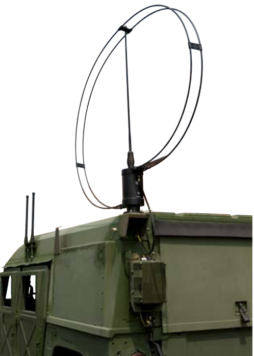
The magnetic loop (magloop, aka. small transmitting loop STL) plays an important role in NVIS communications in that it is pretty much the only antenna that can be used while in-motion due to it’s small size relative to the NVIS operation frequencies’ wavelengths. Its small size also makes it a great NVIS antenna for when antenna setup area is restricted and can even operate inside a garage or attic.
Due to it’s small size it is much less efficient of an antenna on the NVIS bands (especially 80m) compared to 1/4 λ and larger antennas such as a dipole. It also must be tuned nearly every time a frequency change is made due to it’s very high Q. This tuning is done with an air or vacuum variable capacitor that provides a sufficient picofarad value and voltage rating as to be able to create a low swr drop on the frequency in question while avoiding arcing between the rotor and stator components of the capacitor due to the high voltages that the capacitor is exposed to.


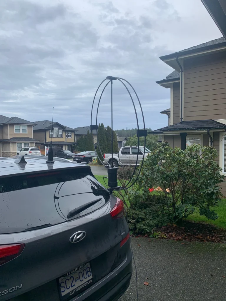
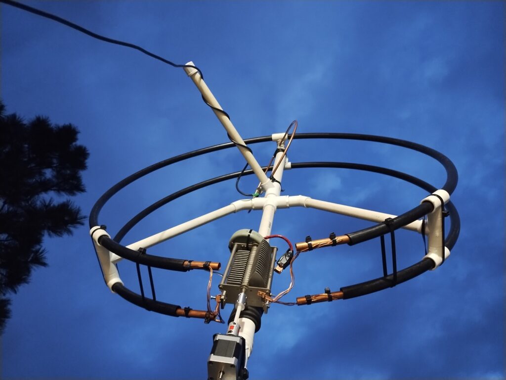
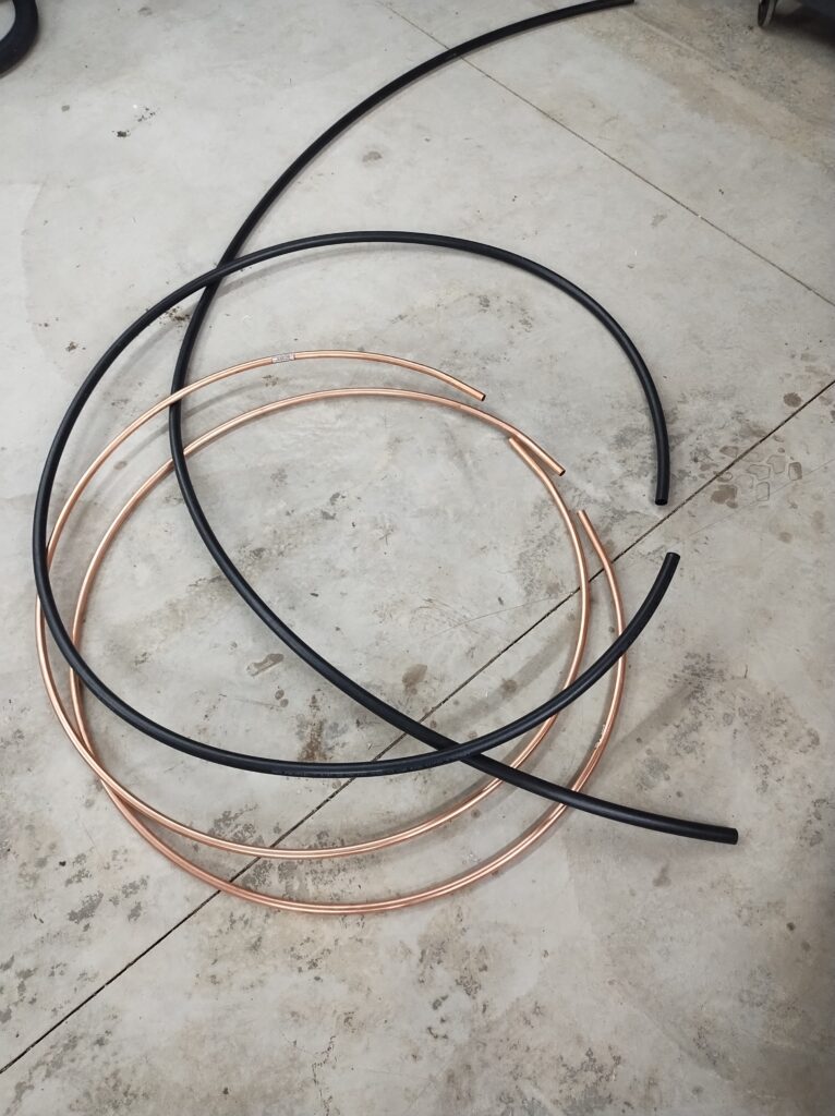
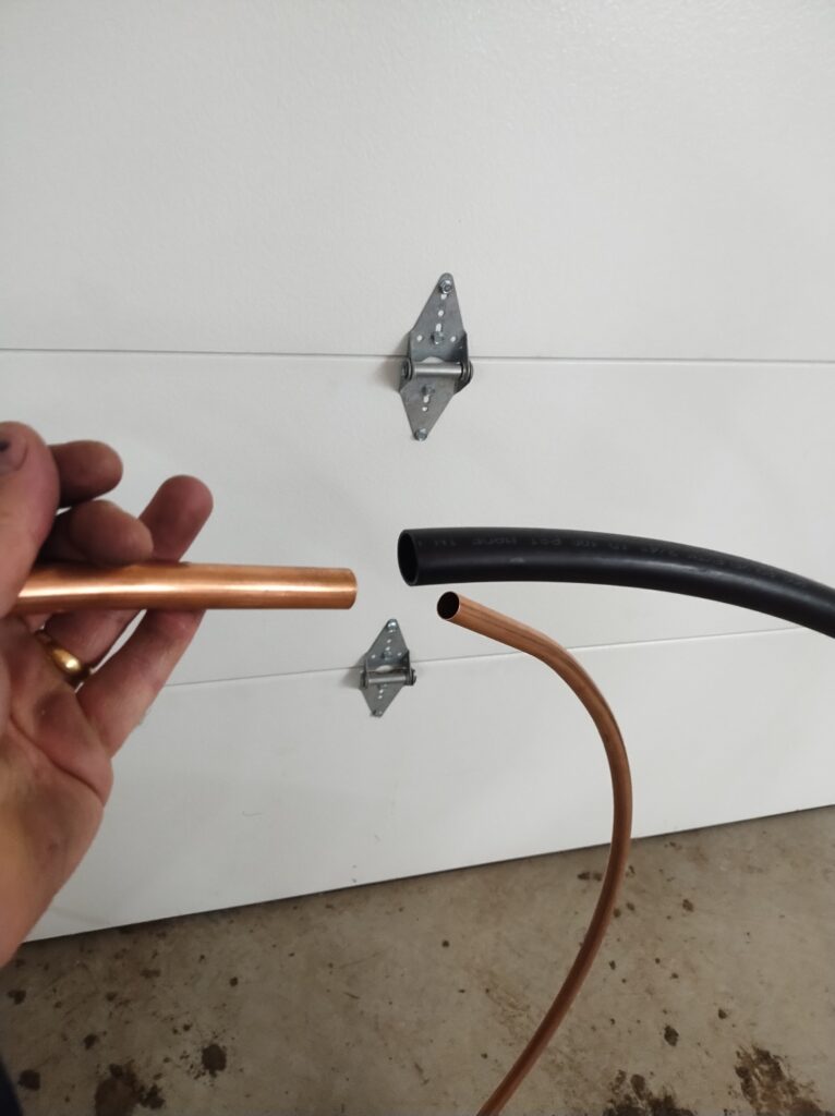
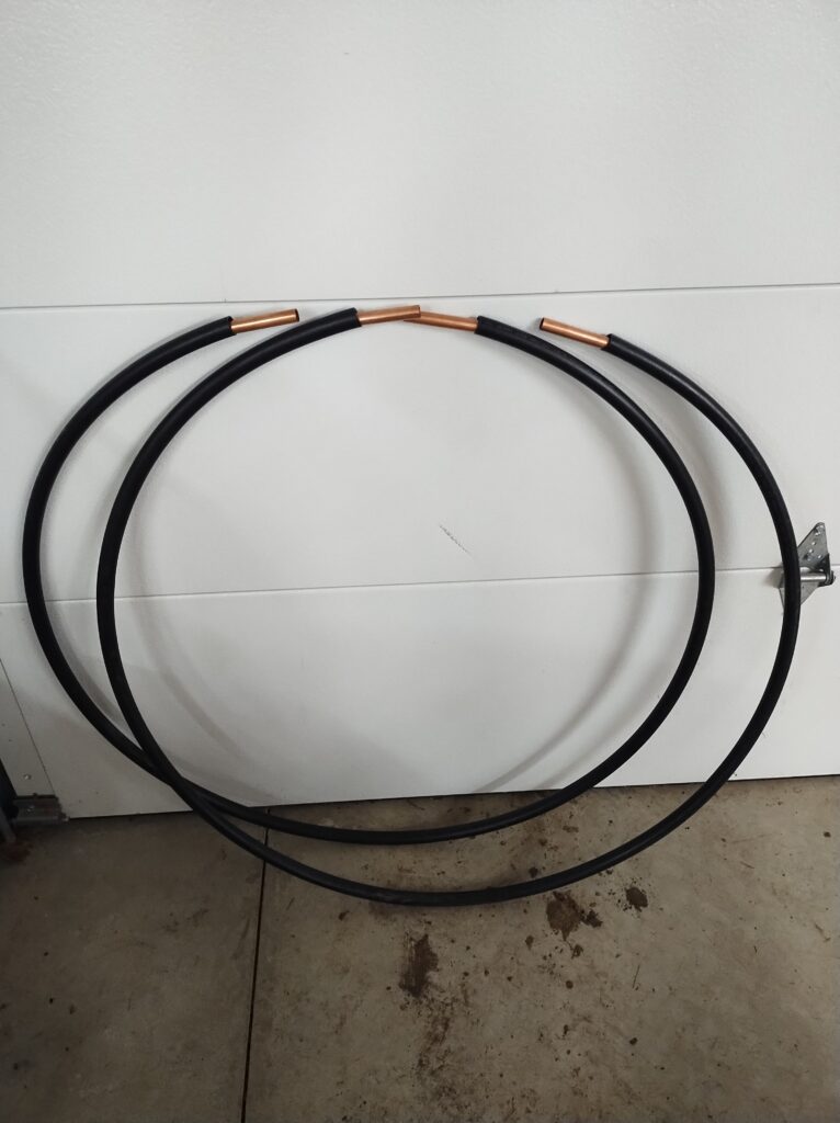
The main loop can be made out of hard or soft copper pipe or RG8 coax with the shield and inner wire soldered together (among other possible materials). One end of the loop is terminated to the stator side of the capacitor and the other is terminated to the rotor side. The feedline connects to a smaller coupling loop (approximately 1/5 the size of the main loop) that is placed inside the loop exactly opposite where the loop connects to the capacitor. There are also other ways to successfully couple the loop but the 1/5 coupling loop is my preferred choice.
How to Design and Construct a Magloop
When designing a loop the first thing to consider is the desired frequency range on which the loop will operate. It is a good idea to try to limit the design to cover a maximum of 3 ham bands for any given loop when using only one variable capacitor. For example, a loop can be designed for 80m/40m/30m or 40/30/20. This limit will allow for one single high voltage air variable capacitor to be used and will allow for acceptable manual tuning.
Any air variable capacitor with enough capacitance range to tune a given loop on 80m/40m/30m/20m, for example, would most likely be made with very narrow plate spacing and therefore have a low breakdown voltage in addition to being very fussy to tune manually due to the larger range the must be adjusted with the same 180 degrees.
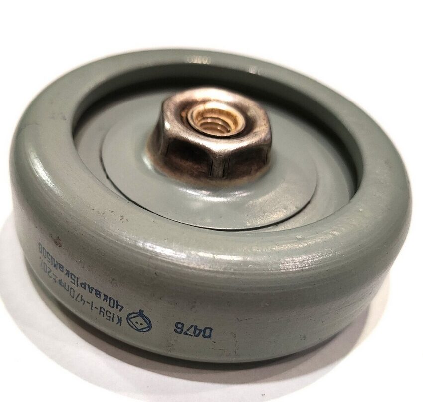
Also, the ability to tune two octaves means that the loop is sized in such a way that the lowest band would experience an extreme reduction in efficiency. If the reduction in efficiency is taken into account a fixed capacitor can be put in parallel to allow for transmission on the lowest band. The three band rule is less in play when applying it to 20m/17m/15m/10m which, despite being 4 bands, is only two octaves.
After deciding upon a frequency range it is a good idea to experiment with the loop calculator spreadsheet created by ham Steve Yates, AA5TB. It can be downloaded below:
If you have existing components already, i.e. a length of RG8, a roll of soft copper, a length of copper pipe, an air variable or vacuum variable capacitor, now would be a time to input your frequency range and the measurements of the lengths of conductor material and begin to see if you can build a loop with your desired frequency range with already acquired components.
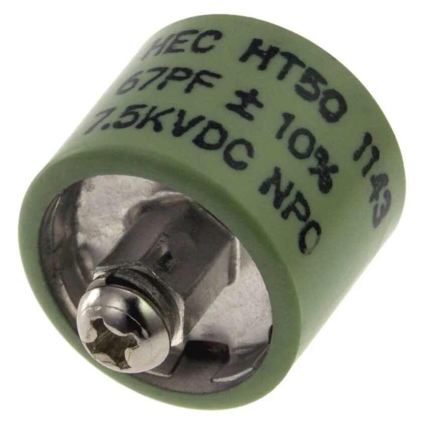
If you are starting from scratch then the first thing to look for is the variable capacitor. Ebay is the best place to buy used/vintage variable capacitors (both vacuum and air variable). Without a variable capacitor there is no way to tune the loop. When you find a variable capacitor that seems to have an acceptable capacitance range, breakdown voltage and price, you can experiment with the loop calculator and the published values to see if will work on your desired bands BEFORE you buy the capacitor. For example:
Let’s say that I want to make a magnetic loop antenna that works on the 40m, 30m and 20m bands. I will only be working the digital portion of the band so I note the LOWEST FREQUENCY on the lowest band that I will possibly work and the HIGHEST FREQUENCY on the highest band that I will possibly work. This will be the high/low range I will use with the various other parameters to see if the capacitor will cover this desired range.
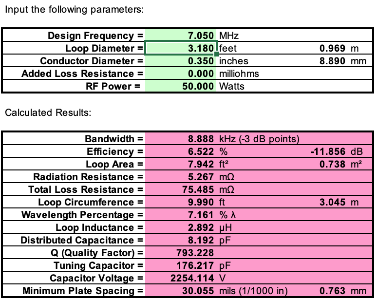
After reviewing the bands and the frequencies that I want to use I find that I will not be needing to tune lower than 7.050 mhz or higher than 14.150 mhz. I also know that I never operate with more than 50 watts. I have decided to repurpose an old 10ft feed line made of RG8 because one of the connectors is broken. I open the loop calculator spreadsheet and input and receive the following data:
I then change the design frequency parameter to 14.150 MHZ (my highest desired frequency) and get the following:
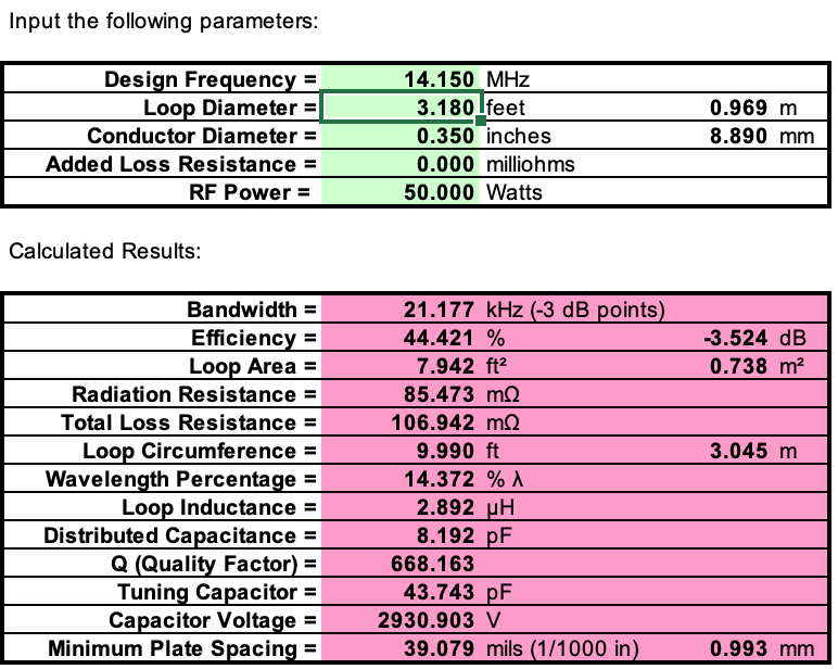
I now know that the variable capacitor that I need MUST be able to provide lower than 47.743 pf and higher than 176.217pf to be able to tune all the frequencies in my desired range. In reality it is better to give yourself a decent margin of error due to factors that can change the actual capacitance (positioning of capacitor, connection wires/position to capacitor, dielectric support insulation etc.) and also the fact that it becomes harder to tune the variable capacitor the closer you are to the extremes of its range. I, therefore, would look for a variable capacitor that could provide 30 picofarads or less and also 200 picofarads or more.
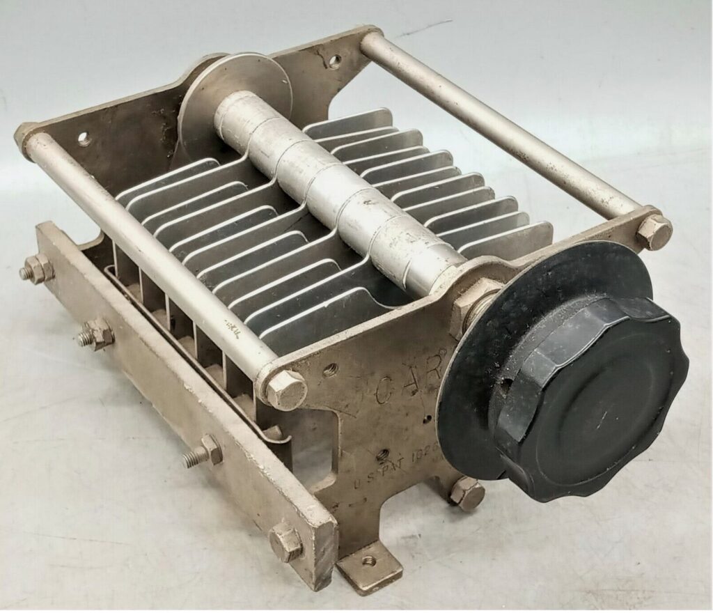
From the computation I also know that if I am using 50 watts on 20m that the voltage produced through the capacitor could reach almost 3000 volts. I check ebay and find a Cardwell air variable capacitor that has a range of 25-220 picofarads and has sufficient plate spacing to have a breakdown voltage of 3000 Volts.
When the air variable capacitor arrives in the mail I check it with a multimeter to verify the capacitance range.
I then take the following steps to build the loop:
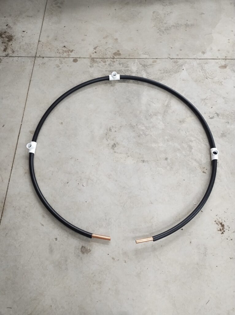
- Remove the insulation that separates the inner conductor from the braid of the 10 ft piece of RG8.
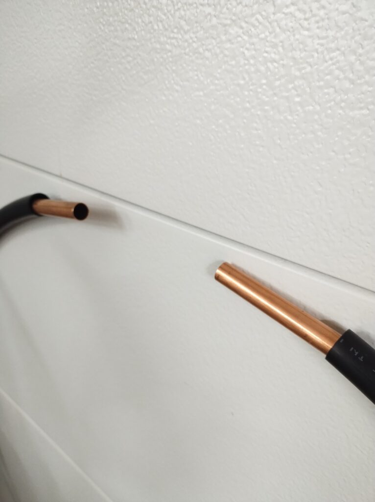
- Connect and solder the braid to the inner conductor on each end of the 10 ft piece of RG8, leaving a few inches of bare copper at each end.
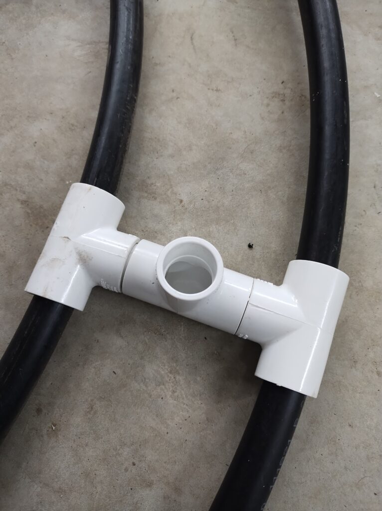
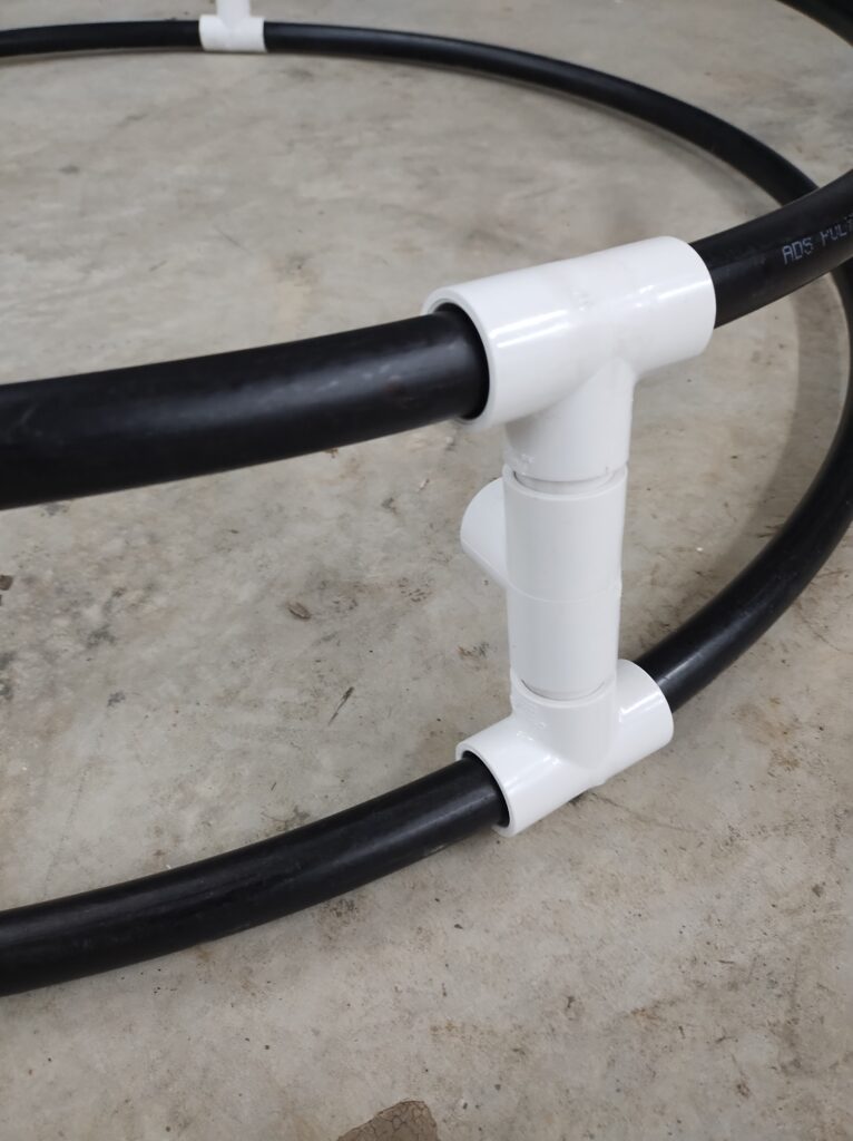
- cut a 6ft piece of 3/4″ schedule 40 pvc pipe and add a pvc tee to one end
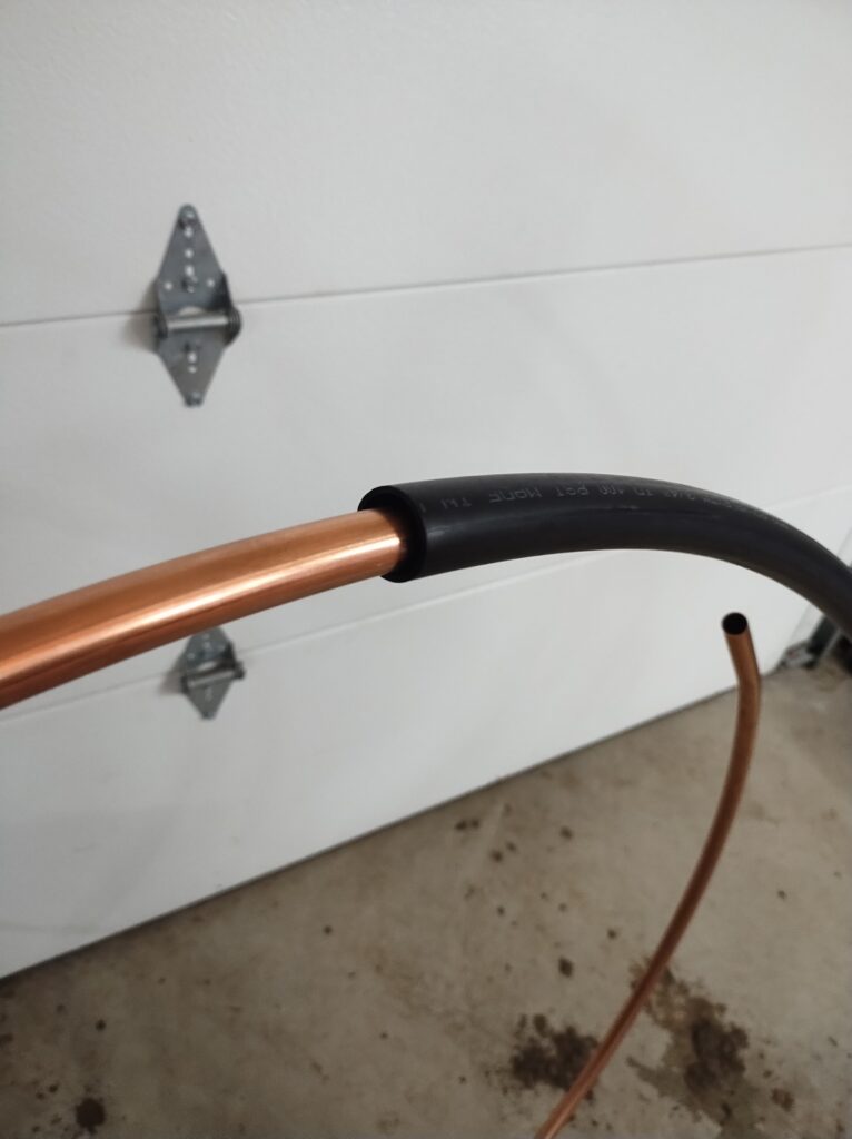
- cut a ~9ft piece of 1/2″ pex tubing
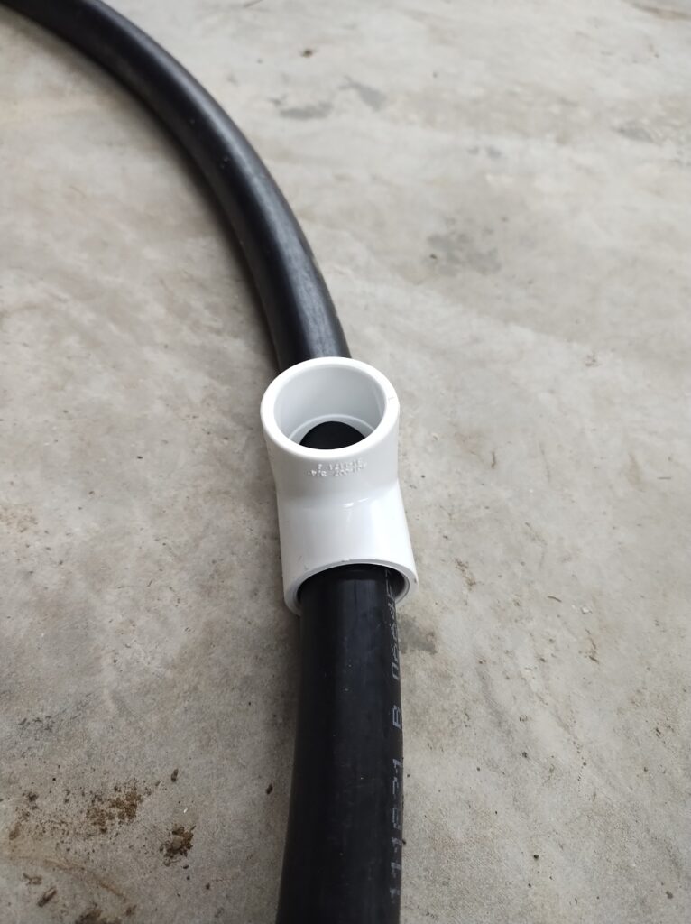
- slip the 10ft piece of RG8 through the 9ft piece of pex tubing and then the RG8 and pex insulator through the 3/4″ tee
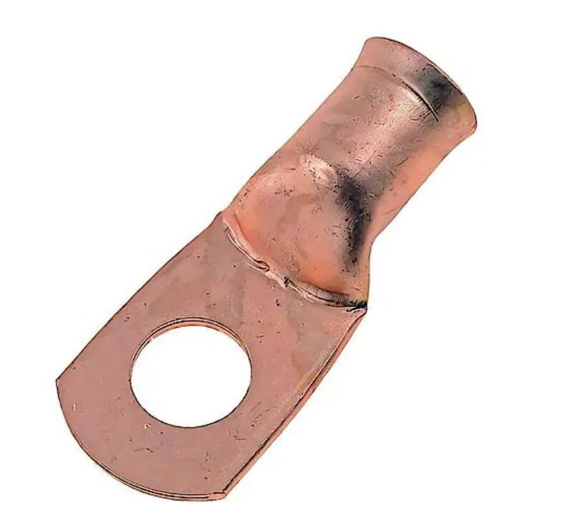
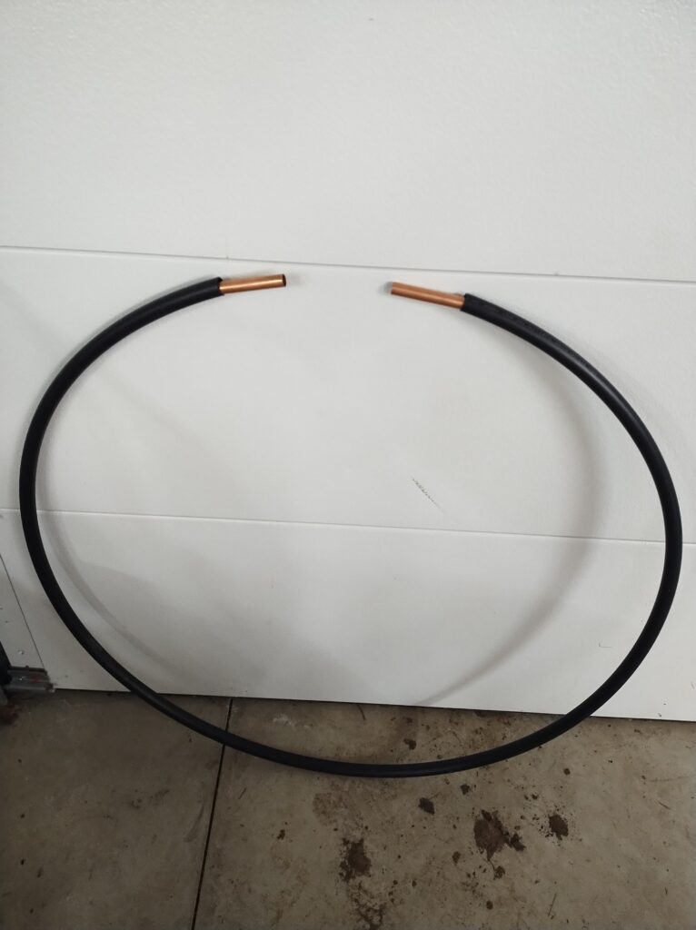
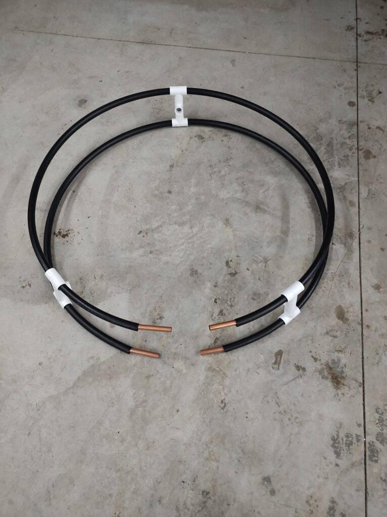
- connect copper lugs to the ends of the the piece of RG8 (you now have completed the main loop!)
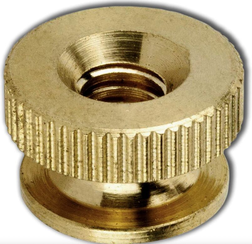
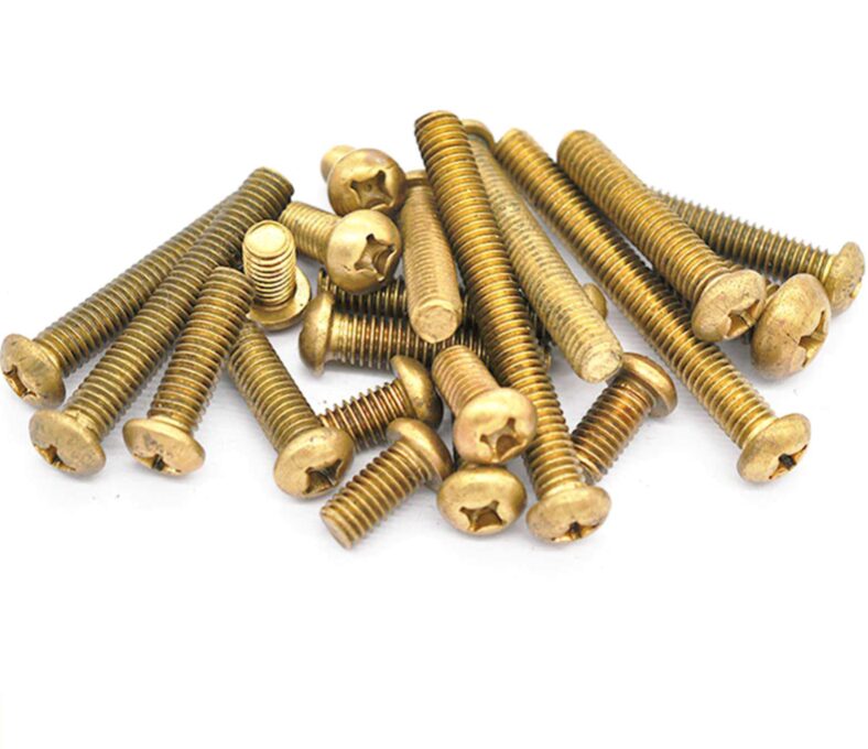
- fasten one side of the RG8 loop (copper lug) with brass nuts/bolts (machine screws) to the stator side of the variable capacitor
- fasten the other side of the RG8 loop to the rotor side of the variable capacitor.
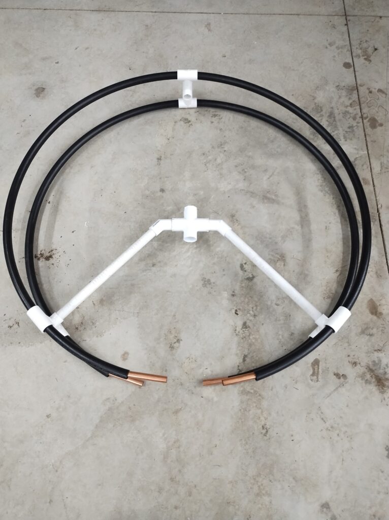
- zip tie or otherwise fasten (with dielectric material) the variable capacitor to the 6ft piece of 3/4″ pvc pipe (to the height where the ends of the loop naturally meet with the pvc pipe)
- center the loop and capacitor and use electrical tape to fix the position of the pex tube to the 3/4″ tee
- build the coupling loop by taking a length of 14 gauge wire or thin soft copper approximately 20% (1/5th) the length of the main loop and soldering one end to center pin of a pl-259 connector and the other to the shield (body).
- affix the coupling loop to the top of the 6ft piece of pvc pipe just below the loop (just on the underside of the 3/4″ tee) with a zip tie, electrical tape or other means
General Considerations When Designing a Magloop Antenna
Loop
- The bigger the loop (diameter), the higher the efficiency, the lower the Q
- The smaller the loop, the more capacitance needed to tune to a given frequency
- The thicker the conductor of the loop, the higher the efficiency, the higher the Q
- The thicker the conductor of the loop, the more capacitance needed to tune to a given frequency
Capacitor
- The closer the spacing of the capacitor plates, the higher the capacitance
- The more capacitor plates there are, the higher the capacitance
- The larger the surface area of the capacitor plates, the higher the capacitance
- The farther the spacing of the capacitor plates, the higher the breakdown voltage
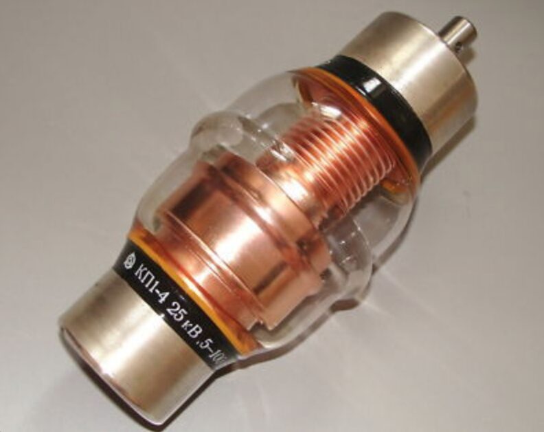
- The breakdown voltage for a vaccum variable capacitor is 10 times higher for a given plate spacing as compared to an air variable capacitor
- An air variable capacitor has no beginning or end and will continuously adjust the capacitance higher and lower when turned multiple times. The full range is available on 180 degrees of the turn.
- A vacuum variable capacitor uses multiple full turns to adjust the capacitance higher or lower and therefore has a beginning (lowest capacitance) and end (highest capacitance).
Helpful notes for constructing a loop
- Zip ties are your friend!
- Eva foam is your friend!
- Wide electrical tape (1″ or 2″) is your friend!
- 1/2″, 3/4″ and 1″pvc pipe (both schedule 40 and thin walled) are your friends!
- 3/4″ poly pipe is your friend!
- pex tubing is your friend!
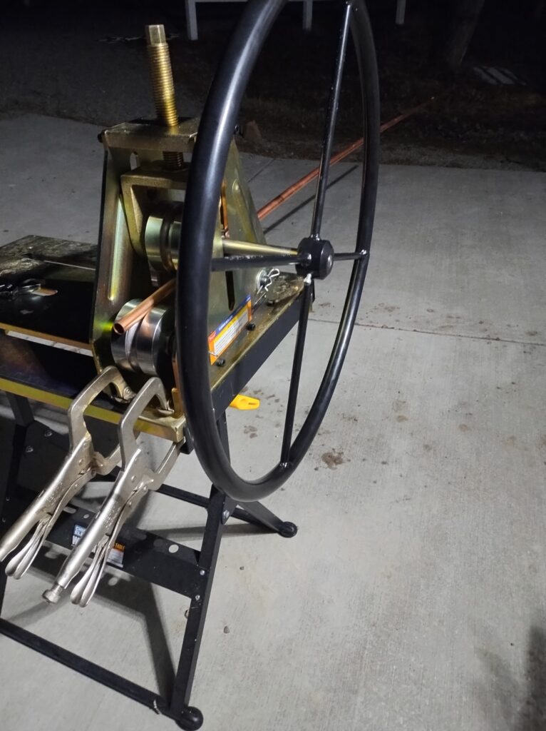
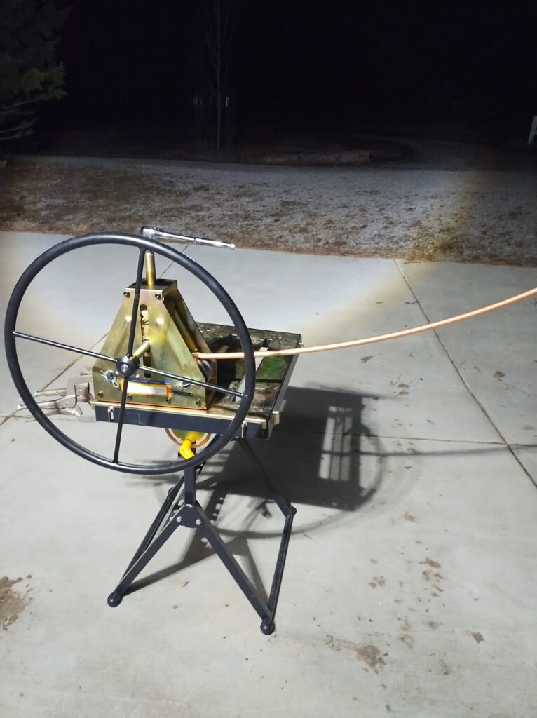
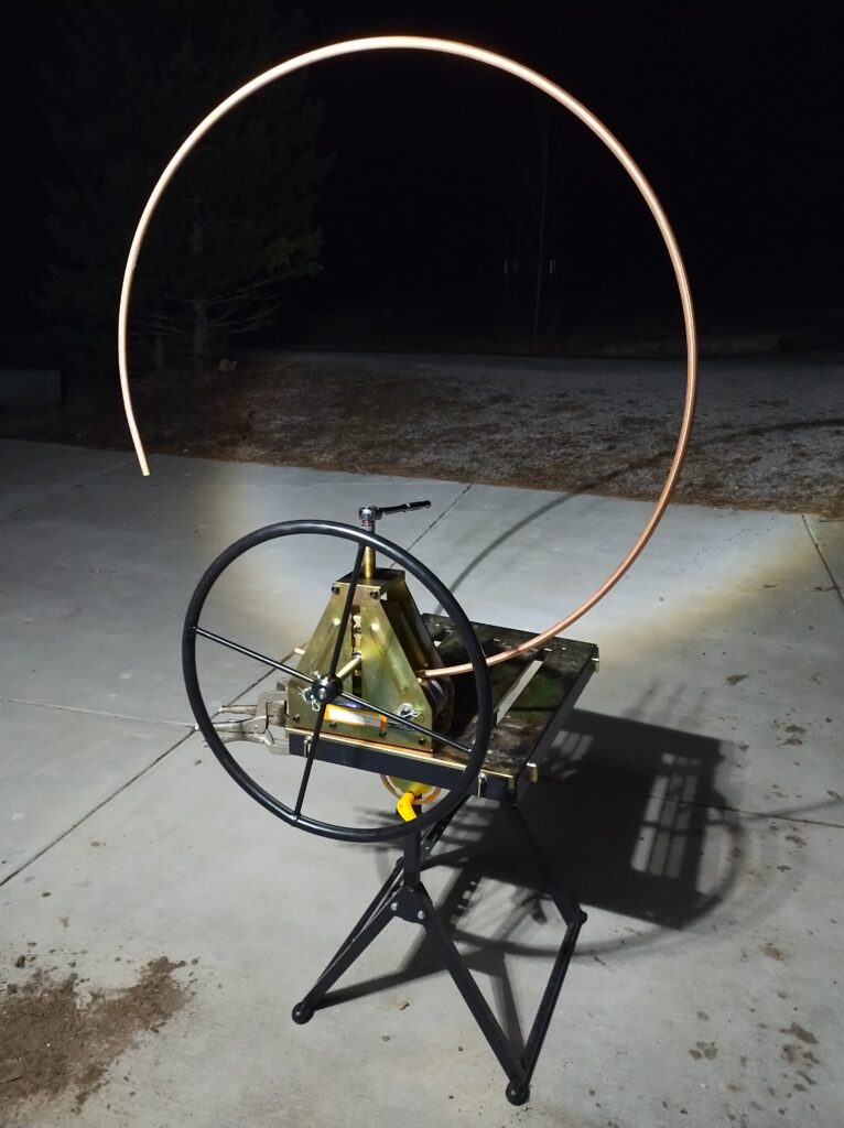
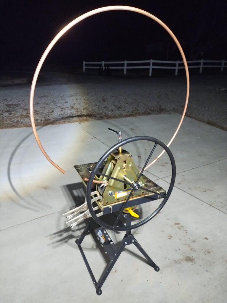
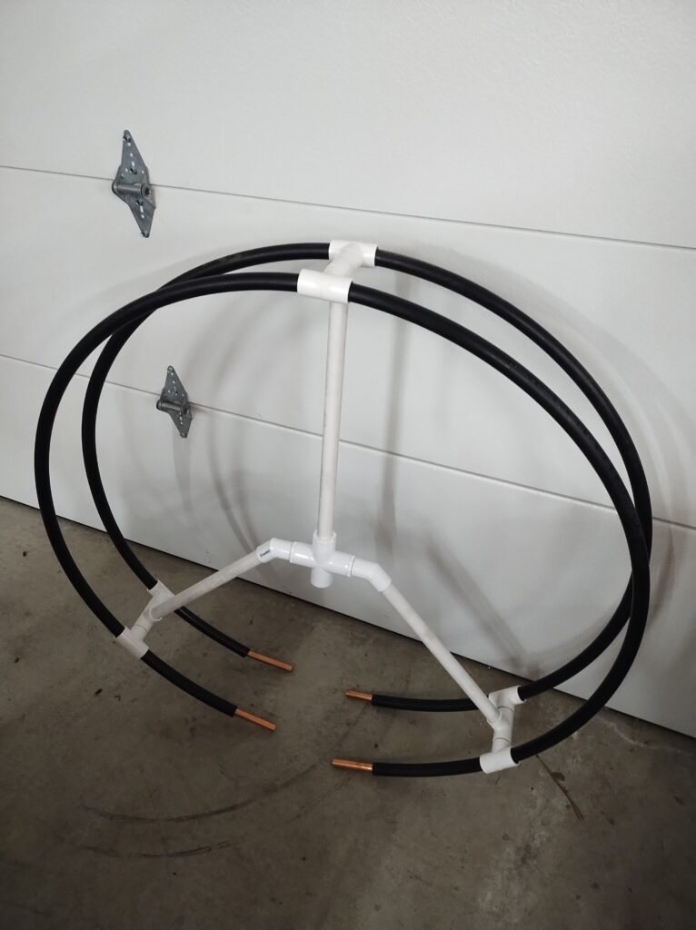
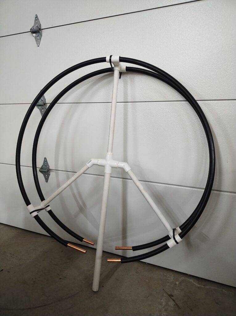
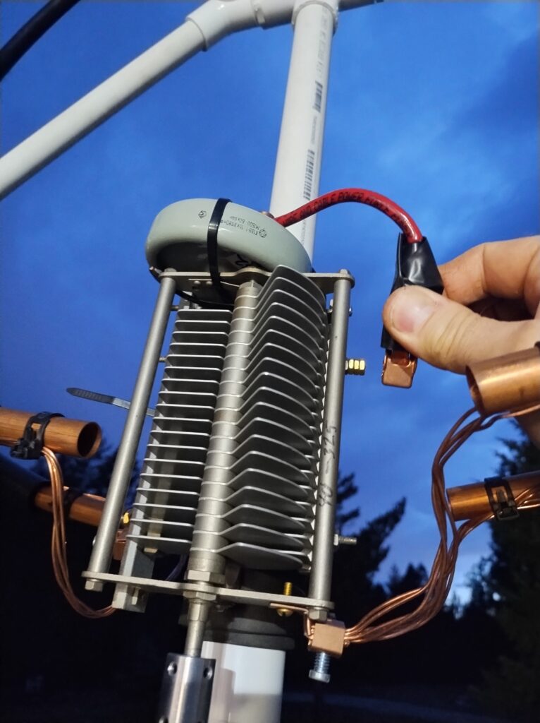
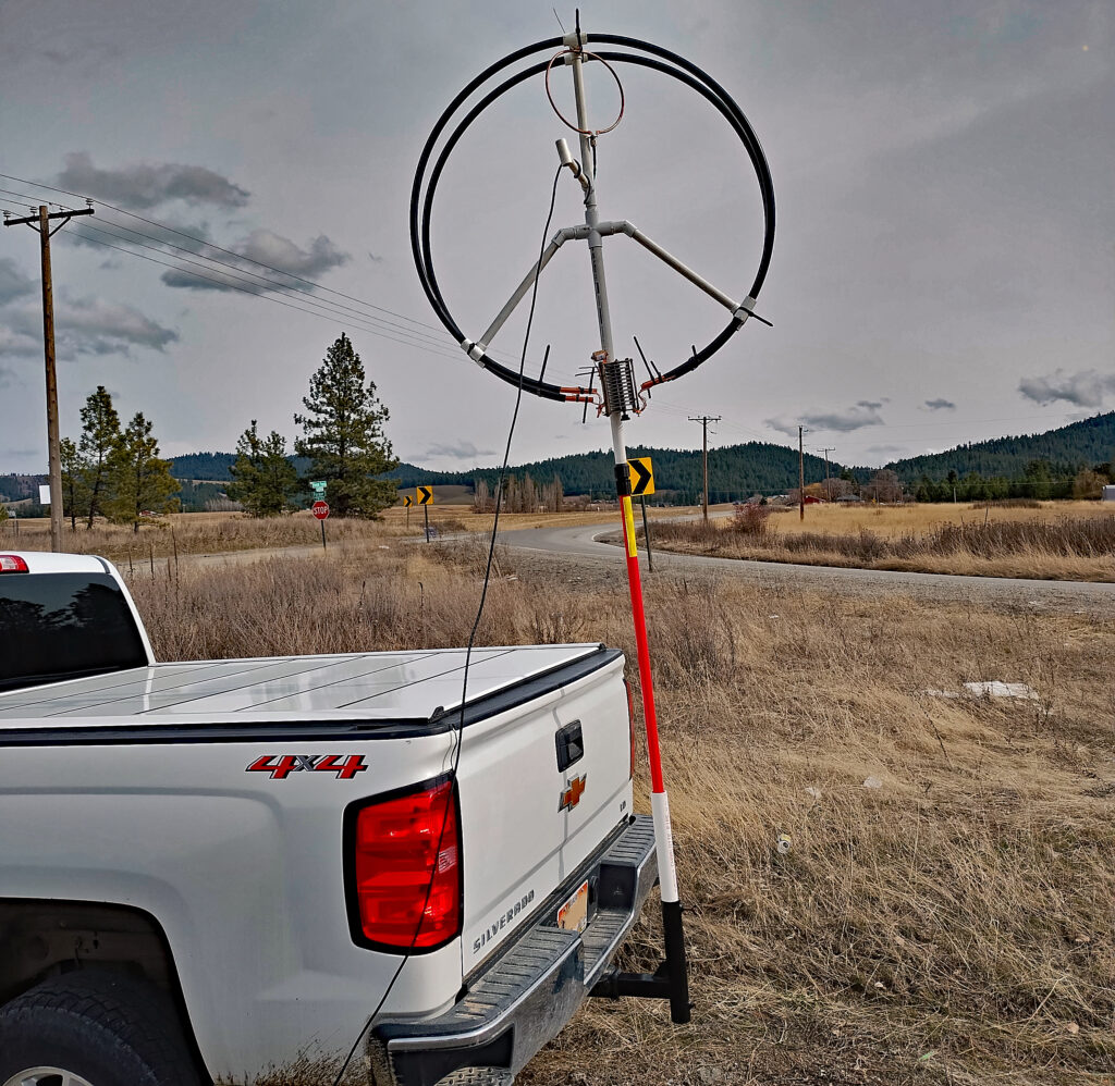
How I built my 10′ circumference (3.18′ diameter) parallel magloop for 80m, 40m, 30m and 20m
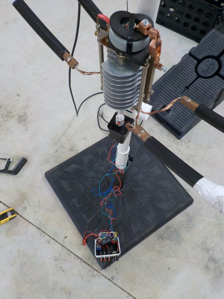
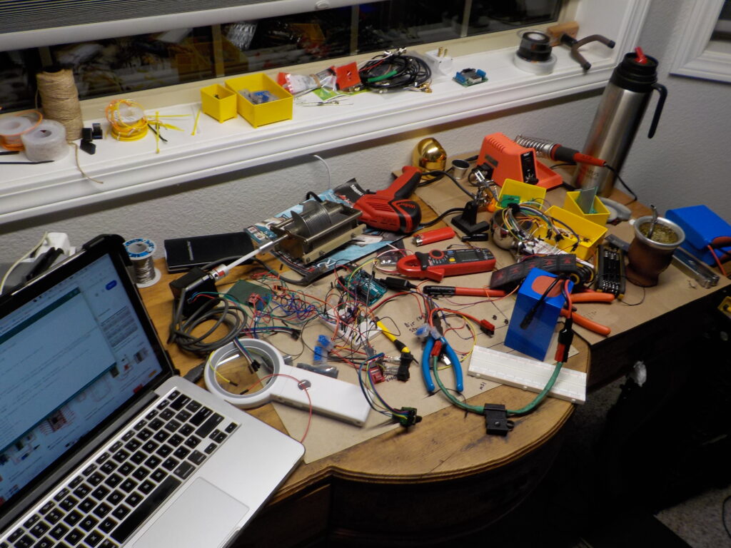
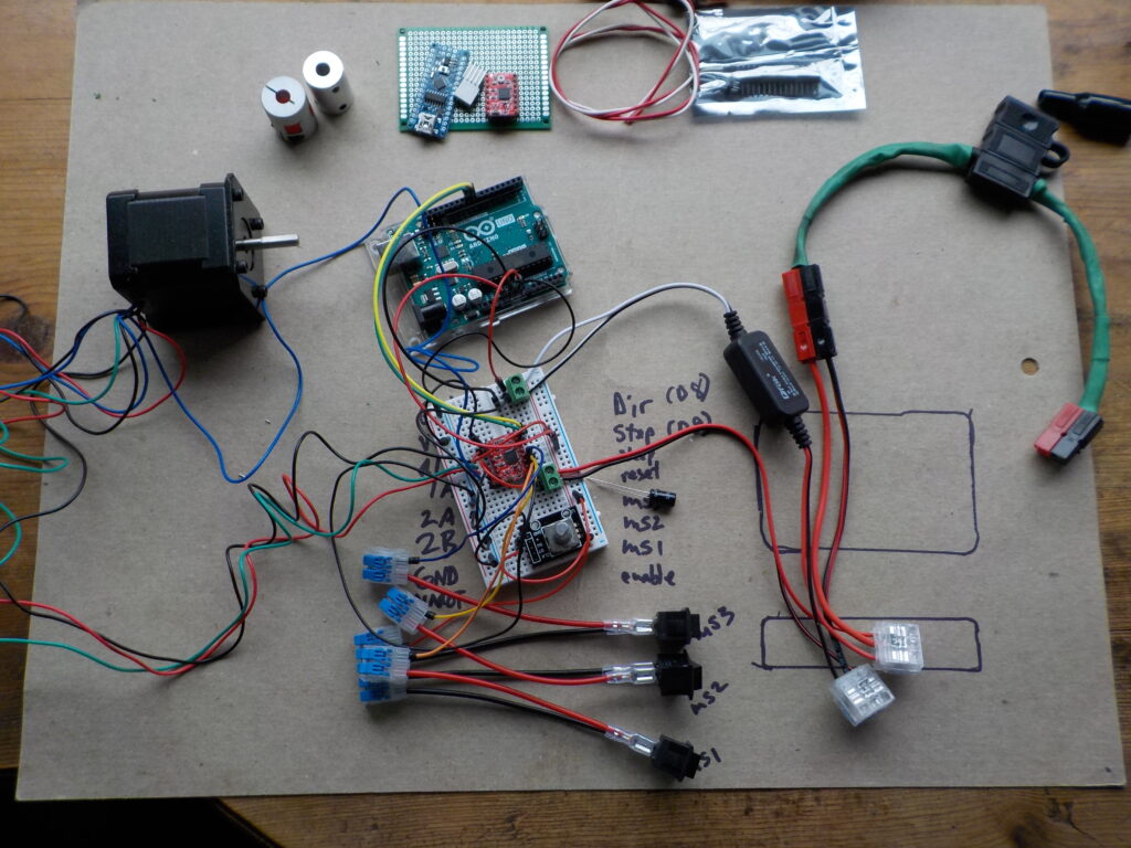
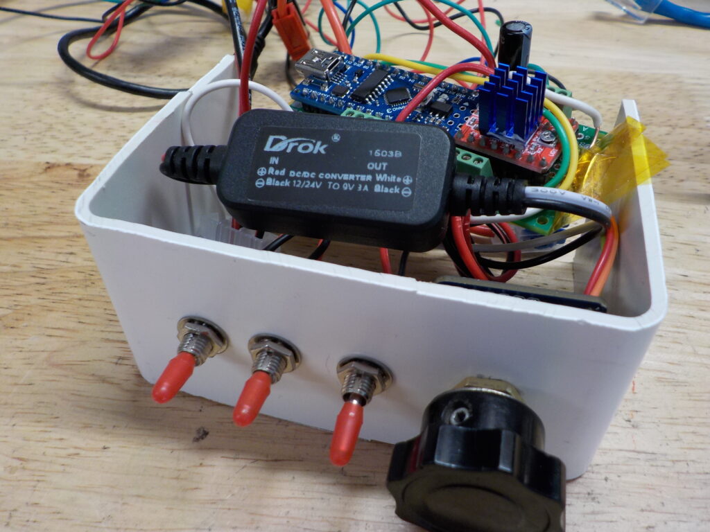
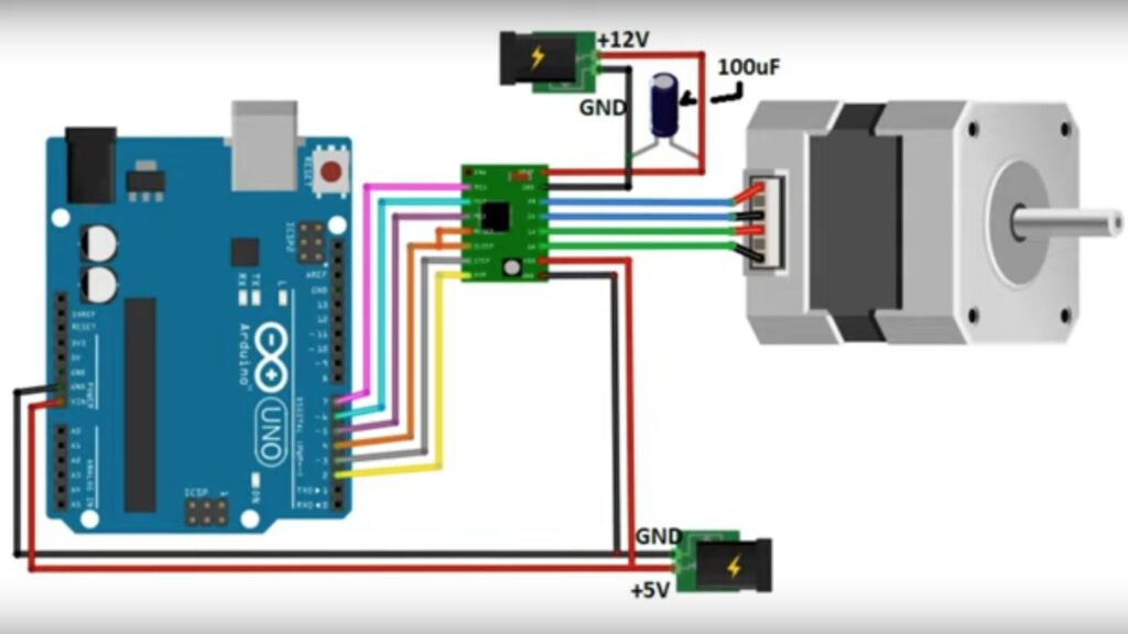
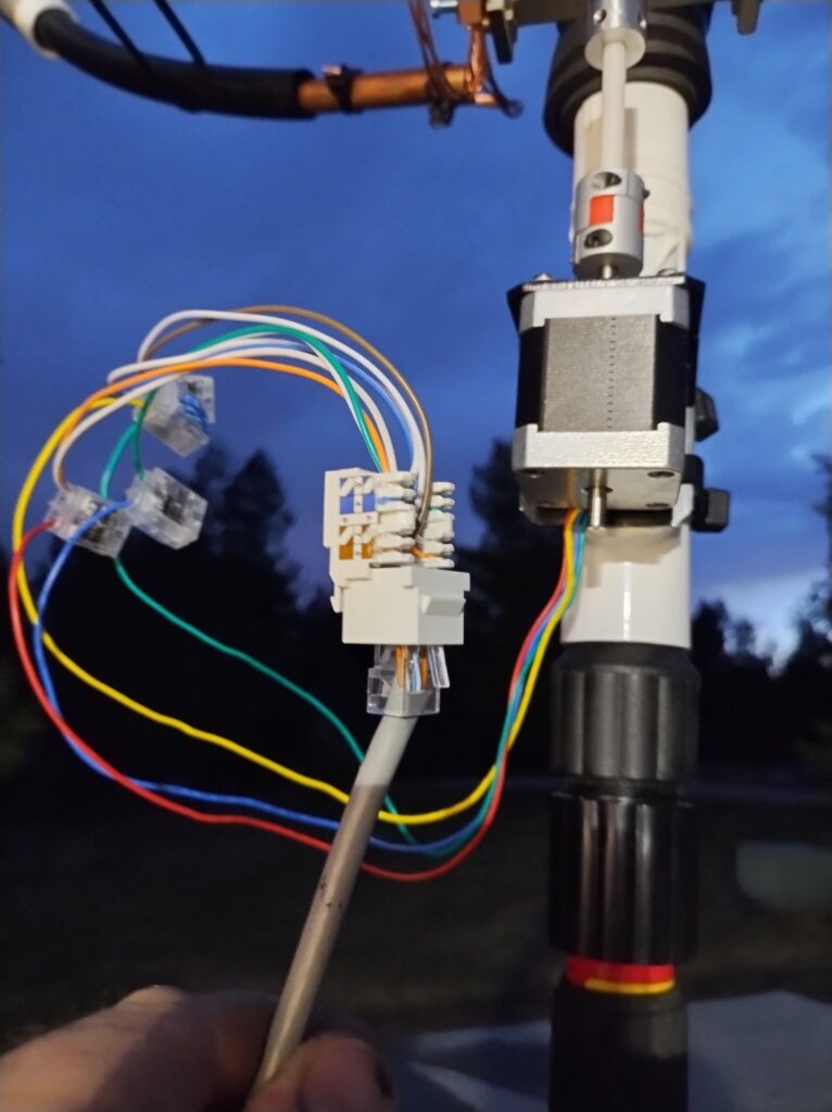
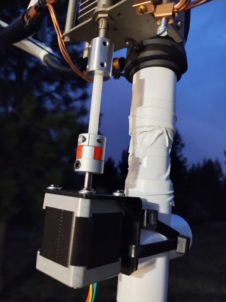
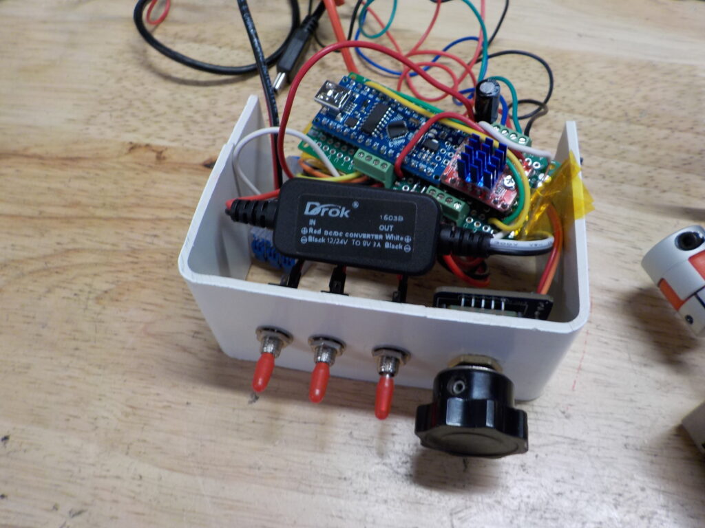
Building and Testing of the Magloop Remote Control Circuit and Stepper Motor

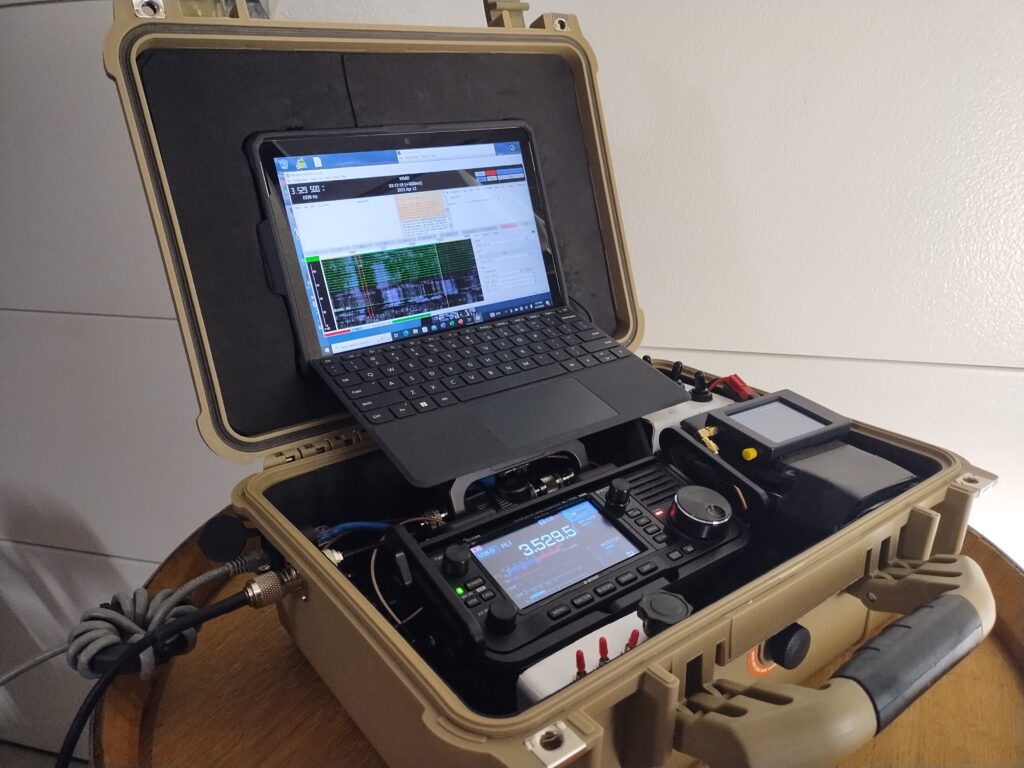
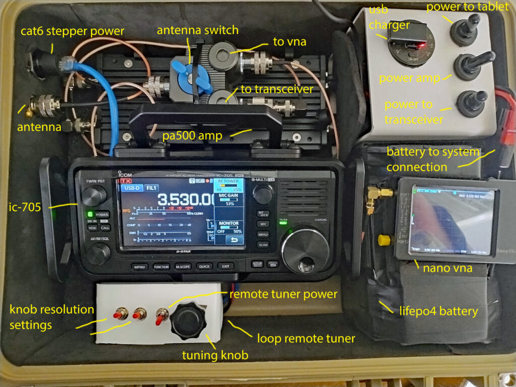
How to Operate the Magloop Antenna System
More than just an antenna the Magloop is an antenna system. The antenna itself is of no use without the ability to tune it, either manually or remotely. The following steps provide a guide to operating the magloop antenna system.
Manual Tuning:
- Tune transceiver to desired frequency
- Plug antenna into vector network analyzer (or switch antenna switch to vna)
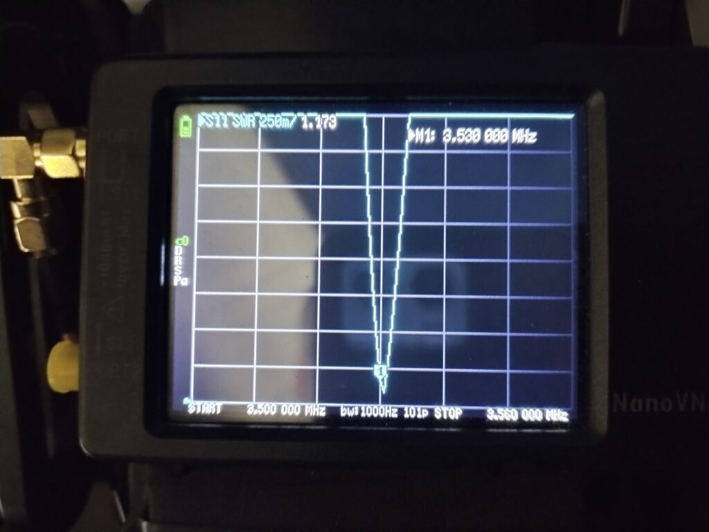
- Select swr frequency range for your desired frequency on vna
- Scroll center cursor to desired frequency with scroll wheel
- Rotate the rotor knob on the variable capacitor until swr dip comes into view
- Tune until cursor lands on the lowest part of the swr dip (when your hand is removed)
- Adjust the coupling loop angular orientation (if needed) to improve swr
- Unplug antenna from vna and connect to tranceiver (or switch antenna switch to transceiver)
- Test swr with a low power setting
- Commence transmission
Remote Tuning:
- Tune transceiver to desired frequency
- Switch antenna switch to vna
- Select swr frequency range for your desired frequency on vna
- Scroll center cursor to desired frequency with scroll wheel
- Turn on loop control and adjust until swr dip comes into view
- Switch loop control to finer resolution
- Fine tune until cursor lands on the lowest part of the swr dip
- Adjust the coupling loop angular orientation (if needed) to improve swr
- Turn off remote loop control (otherwise unbearable QRN will be heard)
- Switch antenna switch from vna to transceiver
- Test swr with a low power setting
- Commence transmission
Things to note when operating/tuning a loop:
- the colder it gets, the higher the capacitance of the capacitor
- If manual tuning: when making contact with the capacitor to tune the loop you will become part of the antenna system and therefore the frequency seen on the vna will seem longer than the actual frequency.
- If remote tuning: the remote loop control must be turned off before receiving/transmitting or the QRN (noise) generated by the circuit will overtake all other sound.
- If using an antenna switch DO NOT forget to switch the antenna from the vna back to the transceiver before transmitting!
Radiation Pattern of Magnetic Loop Antenna
When used on 80 and 40 meters the magloop IS a NVIS antenna. Unless great lengths are taken to raise the magloop high enough to create a lower takeoff angle (for use on 40m) the natural takeoff angle will be straight up.
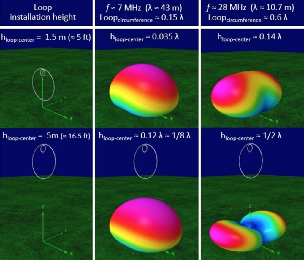
The sheer size of the loop needed to be efficient on 40 meters creates an engineering problem when trying to raise it in the air at least 1/4 λ to favor a lower takeoff angle. This does not mean that you cannot make contacts farther than 500 miles on 40 meters but, for this reason, a magnetic loop would not be a good option for DXing on 40m.
This is not the case for the bands 20 meters and higher. As the desired frequency gets higher the loop gets smaller and the wavelength gets shorter so it is feasible to create a support system (fiberglass pole, hung between two trees, etc.) that would elevate the smaller loop above 1/4 λ. (16ft on 20m, 8ft on 10m).
When the magnetic loop is raised above 1/4 λ, thus producing a lower takeoff angle, the loop will radiate off its ends and have sharp nulls at its front and back.

Testing the Magnetic Loop Antenna
Testing The Magloop Antenna With NVIS Operation
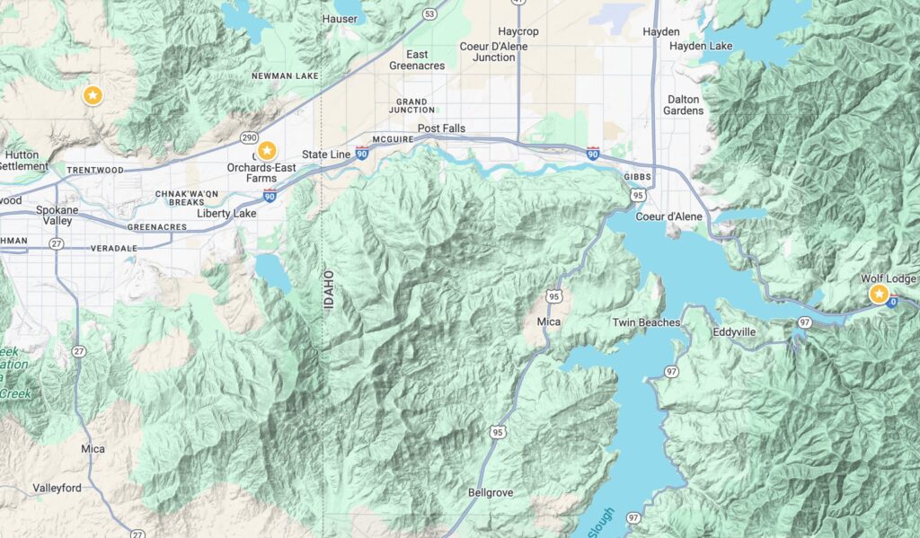
I have been lucky enough to make friends with Dan, NV2Z, who lives in Otis Orchards. Over the past few months we have been experimenting with NVIS propagation at different times of the day, and using different digital modes to see how well we can maintain stable NVIS communication. Most tests have been conducted between his QTH and mine which are located roughly 25 miles apart and separated by various hills and mountains. On one occasion I took the magloop mobile and got approximately 5 miles from his QTH, purposely finding a location with a mountain between us to eliminate any possibility of ground wave propagation. We maintained perfect communication on 40m using FSQ with the output power set to only 2.5 watts. The two locations are shown on the map below.
Loop References and Websites
https://www.nonstopsystems.com/radio/frank_radio_antenna_magloop.htm